June 29, 2015

Weekend Update

Had some time over the weekend to continue working on the ferry dock.  With all the turnouts built, it was now time to focus on the "easy" track.

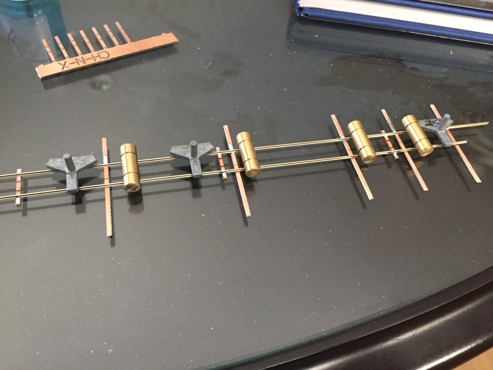
I've become quite fond of the FastTracks "plain old track" jig for making straight track— so it was time to try using it to make the straight section of the pier.  I started by making a simple section, then adding my longer PCB ties to the newly constructed rigid track:


Removing the "standard" ties, I end up with what I want:


Once I had the decking in place, I cut some scribed styrene:


...and fit the pieces between the PCB ties.


As the night drew to a close, I stood up on the chair to check my work against a prototype photo.  My dock is meant to go onto a module, so I'm purposely beefing up some of the framework underneath the deck.  To my eyes, I'm pretty close:


June 16, 2015

Getting back to work

I finally got past some work deadlines and had a chance to build the "easy" turnout for the ferry slip.  Started out with a Fast Tracks #7 turnout template, and a bit of graph paper trimmed to the contours of the dock.


Like the earlier 3-way turnout, I decided to use "extra-long" tie strips that could be blended into the decking.  After a bit of filing and soldering, I spliced the new left hand switch onto the existing track work.  I ended up cutting the ME code 40 rail joiners down to a more reasonable length, but I'm not 100% happy with their appearance.


After I was happy with the splice, I flipped the whole assembly upside down to solder additional bracing to the underside of the PCB ties:


After some tweaking, I now have all the turnouts in place on the dock:


P.S.: Yes, I know I still need to add the throwbar to the turnout.  Next up, continuing the spur that runs down the left hand pier.

April 27, 2015

Crossover indication with DTL logic…

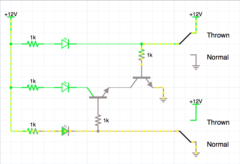
Over on TheRailWire, someone asked if it was possible to create a circuit for indicator LEDs to properly show the crossover route if an only if the turnouts were both aligned using only the half of the DPDT contacts on the turnouts.  Here's a quick Diode-Transistor logic circuit which would use jelly bean NPN transistors (2N2222) to create a simple logic gate for the crossing route:


Both Turnouts "Normal"


One Turnout "Thrown"


Both Turnouts "Thrown"

March 18, 2015

Power routing fun

The 3-way switch has turned out to be a real head scratcher sometimes, but thankfully, I've realized a bunch of the power routing can be done with the existing DPDT contacts on a Tortoise motor.

Here is a look at the various turnout routes and how each section of rail should be powered:


The top "gauntlets" are powered just like a normal switched frog in a conventional turnout. It is just that the left and right turnouts are stacked atop each other. The center frog is powered from either the "left" or "right" routes; and dead otherwise.

Locking out the illegal route is all that is really left to do— and that can be either accomplished by clever software or hardware interlocking.


March 8, 2015

Getting to the Point(s)

Worked on the 3-way turnout again today.  Took a few iterations to tune the points as the constraints are a bit fiddly.  Thankfully the opposite points help act as guardrails and pull the car down the correct path.


The points are "interesting" as they overlap and must be thrown in sequence to set the route:


Next up will be a mechanism to throw those points.


February 7, 2015

Building the 3-way turnout

A productive modeler once told me: "Try to work on your railroad every day, even if it is only for a few minutes."

Taking that to heart, I decided to embark on the something I had been putting off for a few months: building the 3-way switch for the China Basin ferry dock.

I started with a set of paper FastTracks templates (http://www.handlaidtrack.com/Fast-Tracks-Printable-Track-Templates-s/11.htm), cut them up, and taped them together to get a reasonable looking three-way switch:


Using my Xuron flush cutters, files, and FastTracks PointForm/StockAid tools, I spent a few evenings cutting, filing, fitting, and soldering rails. I used Cloverhouse PCB tie strips (http://cloverhouse.com/Store/product_info.php?cPath=35_36&products_id=67) and MicroEngineering Code 40 Rail. I built from the middle rails to  the outer rails, which is the opposite of my usual build order.

First Frogs (#12)

Center Route (Point rails)

Building the Righthand Route

During the build process, it is critically important to check the turnout dimensions using an NMRA Standards gage. A piece of Rolling stock and/or truck is also very helpful.

After a few nights, I managed to get the rest of the rails in place:


At this point, you are probably saying, "Why the 3#@k is he using such long PCB ties?"  Well, they say that a picture is often worth 1,000 words, so here you go:


Next steps will be to get that nested set of points to throw properly... more on that soon.

January 5, 2015

Building the Pilings

The next phase of the ferry dock was building the piling walls along the inside edges of the dock.

In a departure from the plastic construction I had been using to build the trestle sections, I decided to try my hand with using real wood to represent wood.

First, I stained 3/16" hardwood dowels using thinned Vallejo Model Color 70-822 German Black Brown:


After cutting an insane number of pilings, I got out some "dark wood" carpenter's glue (it dries brown instead of yellow) and started to assemble the wall.  Working from photos, I realized that the pilings needed to be spaced apart AND an extra layer of angled timbers were used to tie the wall together:


I really liked the look of the wood, but then I realized the next phase of the problem— I needed to paint the white plastic trestle sections.

As a test, I took the thin section of the dock, and painted it with Games Workshop Chaos Black primer, then began dry brushing Vallejo paints over the black.  I ended up dry brushing over the primed dock with the 70-822 German Black-Brown and 70-871 Leather Brown.


Here's a better look at the progress so far (with the barge for a reference):


November 30, 2014

It has been a while since the last post, so I thought I'd share an update on my China Basin project.

A few weeks ago, I had a few hours to play with the Epilog laser cutter at TechShop San Jose.  My first attempts at laser cutting after a year or two away from the machine served as an opportunity to re-learn the practical limits of laser board on the heavily used machines.

I tried cutting some of the superstructure and gears, but ended up with parts that were burned and fragile— I had forgotten to consider the thickness of the laser beam itself.


After tweaking the CAD a bit, I increased some of the dimensions, ran a few more cuts, and ended up with a pile of laserboard widgets to play with.  I had to head home, as my two hours of reserved time were over.


After playing with the parts, I had decided that there was no good way to build a "fold-up" model of the gantry crane.  I also had my doubts about the strength of the resulting construction, as this would eventually end up on a Free-moN module.

A few days later, resigned to the concept that I may need to abandon the laser, I started playing with Plastruct parts.


While the model was sturdy, it looked a bit too "beefy" for my taste— as I was starting to consider building the latticework on the front face, I stumbled upon another idea.  I had posted the work in progress to the Model Rail Radio Facebook group, and Jimmy Simmons said it looked good, but he'd stick to his laser.  Then it hit me— why not combine the two techniques.

As part of the earlier laser cutting attempts, I ended up with a few individual pieces that might work:


As a quick hack, I decided to glue up the laser cut faces to the plastic, and the results were quite pleasing to me:


I was psyched— a few weeks of the project sitting on the back shelf inspired me to get back into it.  The next step was to try out the gluing up multiple laser cut parts into the large pulleys used at the top of the gantry:


Some good progress on the difficult bits inspired me to get back to building more pilings, and the test fitting the works on the dock:


All in all, it was a productive Thanksgiving weekend— I hope to make more progress during Christmas break when I'll have more time to devote to the project again.
November 3, 2014

Ferry Slip Update

Had a chance to work on paper mock-ups for the "business end" of the ATSF slip.  Initial paper models were a bit too small, and didn't have enough clearance, but after working with the "full scale" drawings and my NMRA gauge, I think I have the right "look":


Spent some time learning how to vaporize laser board at the TechShop— it is going to take a few more hours to learn what I can get away with.  Here is a look at what happens when you try and cut things that are a bit too small:


Planning on going back for more learning/punishment next weekend to dial in the settings and tweak the CAD a bit.

September 28, 2014

Phone Booths

Added a quick coat of paint over the black primer to Robert's SLA phone booths:


Look forward to installing these line side next Friday.